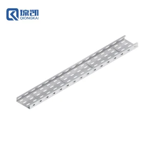
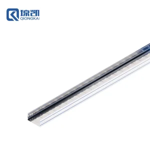
Factory Catalog · Phase I
Standard & Heavy-Duty Structural Trays
Direct supply from Shanghai Qiongkai Industry Co., Ltd. — Engineered profiles manufactured for strict span-to-deflection ratios in commercial and hazardous installations.
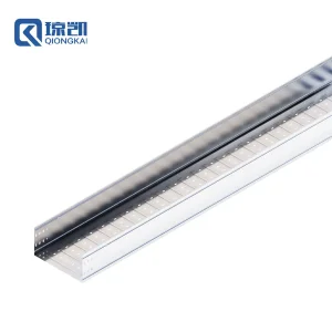
Cost Saving Heavy Duty Molded Pre Galvanized Tray 400*200
View Specifications
Wholesale UPVC 100*50 Cable Trunking Lightweight System
View Specifications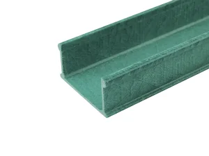
Corrosion-Proof FRP Cable Trunking 200*100 mm
View Specifications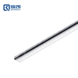
Reinforced Molded PG Cable Trunking Trough Channel 100*50
View Specifications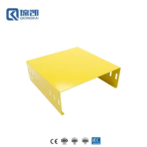
Powder Coated PG Trunking Channel RAL1080 Yellow 300*100
View Specifications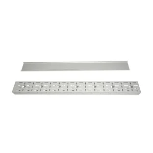
Stainless Steel 316/316L Maximum Perforated Cable Tray
View Specifications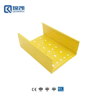
Powder Coated Reinforced PG Tray RAL1080 Yellow 200*100
View Specifications
Structural Dynamics & Beam Theory
Engineering Cable Tray Support Spacing: Physics, Standards & Cost Optimization
In mega-infrastructure projects, determining support distance is not simply a matter of aesthetic layout; it is a structural calculation governed by bending moments, shear stresses, and deflection limits under full cable mass and environmental impact.
Elastic Bending & Deflection Sizing
Under continuous load conditions across multiple spans, structural deflection must not exceed L/200 (or L/360 in sensitive optical fiber routing) as mandated by NEMA VE-2. Spacing dictates the modulus of rupture, determining whether side-rail web height must be increased from 50mm to 100mm or 150mm.
Dynamic Thermal Displacement
In applications spanning desert solar arrays or offshore LNG platforms, temperature deltas of up to 60°C cause severe longitudinal thermal expansion. Correct support distances incorporate slotted thermal expansion splice plates positioned at 0.211L from support stanchions for zero moment equilibrium.
Dynamic Point Loads & Pull Tension
Beyond distributed cable dead load ($W$), installation dynamics exert transient concentrated pull forces ($P = 90 \text{ kg / } 200 \text{ lbs}$) at mid-span. Supplying engineered continuous beam profiles ensures that factor of safety (FoS) remains $\ge 1.5$ during cable pulling operations without permanent plastic deformation.
Empirical Beam Equation Reference: Support Distance & Safe Working Load (SWL)
For a continuous uniformly distributed load $w$ over span $L$, the maximum bending moment occurs at interior supports: $M_{max} = \frac{wL^2}{10}$, with maximum deflection at the center of exterior spans given by $\delta_{max} = 0.0068 \frac{wL^4}{EI}$. Increasing support distance from 1.5m to 3.0m quadruples the deflection and quadruples the bending moment, demanding high Section Modulus ($Z$) profiles or high-tensile hot-dip galvanized side-rails.
20+
Years Manufacturing Excellence (Since 2005)
30,000m²
Production Floor across 3 Dedicated Facilities
12
Automated Cold-Roll Forming Assembly Lines
60+
Heavy-Duty Hydraulic CNC Stamping Units
Empirical Lookup Table
Standardized Support Distances Across Cable Tray Material Classes
Comprehensive engineering guideline aligned with IEC 61537:2021 and NEMA VE-1 load class ratings. Values represent safe continuous spans under full rated conductor loads with a 1.5 safety factor.
| Profile & Material Matrix | Recommended Support Spacing | Safe Working Load (SWL) | Permissible Deflection | Global Compliance Standard |
|---|---|---|---|---|
| Pre-Galvanized (PG) Light Perforated (100x50mm) | 1.2 m – 1.5 m (4 – 5 ft) | 60 kg/m (40 lbs/ft) | < 6.5 mm at mid-span | IEC 61537 Type I |
| Reinforced HDG Heavy-Duty Perforated (400x100mm) | 2.0 m – 2.5 m (6.5 – 8.2 ft) | 160 kg/m (107 lbs/ft) | < 10 mm at mid-span | NEMA VE-1 Class 12C |
| Industrial Cable Ladder (Steel / HDG Side-Rail 150mm) | 3.0 m – 6.0 m (10 – 20 ft) | 240 kg/m (161 lbs/ft) | < 15 mm at mid-span | NEMA VE-1 Class 20C |
| Pultruded FRP / GRP Polyester Composite (200x100mm) | 1.5 m – 2.0 m (5 – 6.5 ft) | 110 kg/m (74 lbs/ft) | < 8.0 mm at mid-span | ASTM D635 / UL94 V-0 |
| Marine Grade Stainless Steel 316L Mesh Tray (200x50mm) | 1.5 m – 2.0 m (5 – 6.5 ft) | 75 kg/m (50 lbs/ft) | < 7.0 mm at mid-span | DNV-GL Marine Rules |
| Rigid UPVC Flame-Retardant Trunking (100x50mm) | 0.9 m – 1.2 m (3 – 4 ft) | 35 kg/m (23 lbs/ft) | < 4.0 mm at mid-span | BS EN 50085-1 |
Selecting an experienced manufacturer is paramount when specifying spans greater than 3.0 meters (extra-long span ladder trays). Shanghai Qiongkai Industry Co., Ltd. produces structural cold-formed profiles with deep sidewall returning ribs and cold-welded I-beam side runners that reduce material volume by up to 18% while maintaining identical section moduli ($S_x$), significantly lowering the total installed cost of trapeze hangers, cantilever brackets, and structural steel attachments across commercial and industrial facilities.
Structural Safety Assurance
Seismic Bracing, Localized Building Codes & Field Topology
How seismic acceleration forces ($S_{DS}$), wind shear, and local mechanical codes dictate secondary support and anchoring intervals.
Seismic Sway Restraints (ASCE 7-22)
Standard gravity trapeze supports every 2 meters do not protect against lateral shear. For high seismic zones (IBC Seismic Design Category C through F), lateral seismic bracing is engineered every 9m to 12m, with longitudinal bracing placed every 18m to prevent dynamic catastrophic buckling of the run.
Strut Channel & Trapeze Modularity
By pairing cable trays with Qiongkai's cold-formed 41x41mm and back-to-back 41x82mm unistrut channels, installation crews adjust hanging rod centers dynamically. Anti-slip serrated channel nuts guarantee static torque ratings up to 45 N·m under heavy mechanical vibration.
International Marine & EPC Approvals
From QatarEnergy LNG offshore pipelines to Milan commercial transport lines, Qiongkai finishes (HDG with ≥86μm zinc coat per ASTM A123, SS316 pickled/passivated, and fire-resistant UV-inhibited FRP) guarantee complete resistance against pitting corrosion and micro-cracking across 25+ year design lives.
Supply Chain Transparency
Engineering Powerhouse: The Shanghai Qiongkai Factory Ecosystem
Precision cold-roll engineering, automated robotic welding, and turnkey BIM-coordinated support schedules for international contractors.
BIM Level 400 & FEA Stress Mapping
We supply accurate 3D Revit families and finite element stress analysis for custom configurations. By calculating exact bending stress concentrations around elbow fittings and tee intersections, we help consultants identify precise hanger placement before site work commences.
Automated Cold-Roll Profiling
Our 12 continuous roll-forming lines feature progressive multi-station tooling that stamps ribbed side rails with cold-formed hemmed edges. This process creates smooth edges that protect cables from insulation abrasion while boosting stiffness along the neutral axis.
Custom High-Tolerance Fabrication
From custom 900mm wide ladder trays for Italian distribution hubs to composite FRP trays for harsh chemical plants in Thailand, our engineering department provides rapid prototyping, mill test certificates (MTC per EN 10204 3.1), and third-party Lloyd’s or SGS inspection support.
Technical FAQ
Frequently Asked Questions: Cable Tray Support Distances & Sourcing
Actionable structural and procurement insights curated by senior application engineers.
What is the maximum standard support distance for industrial cable trays?
Under standard NEMA VE-2 and IEC 61537 recommendations, commercial perforated cable trays and cable trunking are designed for supports spaced at 1.5m to 2.0m (5ft to 6ft) intervals. Industrial ladder trays with enhanced sidewall heights (100mm to 150mm) can safely support runs across 3.0m to 6.0m (10ft to 20ft) spans. Support spacing must always correlate with the combined total linear mass of cables (kg/m), expected ice or wind loads, and mid-span live load requirements.
Where should cable tray splice plates be located relative to supports?
Splice joints should never be placed directly over a support or at true mid-span. Structurally, the optimal placement for a splice plate is at approximately one-quarter of the span length (0.211L to 0.25L) from the support. At this inflection point (the zero-moment point of a continuous beam), bending moments are minimized, preventing splice hinge failure and minimizing joint deflection.
How does support distance change when routing heavy power cables versus lightweight data cables?
For high-voltage armored cable (XLPE/SWA), weights can exceed 80–120 kg/m, requiring supports every 1.2m to 1.5m to stay within structural deflection thresholds. Data hall environments routing CAT6A or fiber optic cables in wire mesh basket trays have lower weights (15–30 kg/m), allowing supports to be spaced at 2.0m to 2.4m, provided bend radii at drop-outs are supported with dedicated bracketry.
How do factory material selections affect allowable support span distances?
Steel has a Young’s Modulus ($E$) of roughly 200–210 GPa, whereas pultruded FRP composite has a modulus of 17–28 GPa, and aluminum alloys hover around 69 GPa. Consequently, an FRP or aluminum tray requires closer support intervals (typically 1.2m to 1.8m) to achieve the same deflection resistance as a heavy-gauge galvanized steel tray, unless the composite profile incorporates taller side rails.
Why is hot-dip galvanizing after fabrication (HDG) preferred over pre-galvanized (PG) for long outdoor spans?
Pre-galvanized sheet (standard EN 10346, ~15–20μm zinc layer) is cut and punched at our factory, exposing bare carbon steel edges. While zinc provides galvanic edge protection in dry indoor settings, outdoor or coastal environments will oxidize these cut faces. Hot-dip galvanizing after fabrication (ISO 1461 / ASTM A123) immerses the entire finished unit into 450°C molten zinc, producing an 80–100μm metallurgical alloy layer across all holes, edges, and welds for extended exterior service.
What parameters are needed when requesting a custom span design from Qiongkai?
To provide an accurate structural proposal and bill of materials (BOM), please provide: (1) Total linear weight of cables (kg/m), (2) Target support span interval (e.g., 2m, 3m, or 6m based on structural column bays), (3) Installation environment (chemical plant, offshore, indoor data center, or outdoor solar), (4) Desired deflection limit (e.g., L/200 or L/360), and (5) Local seismic or wind load requirements.
Factory Catalog · Phase II
Wire Mesh, Ladders, Covers & Specialized Profiles
Explore additional manufactured solutions engineered for continuous support spans, overhead data routing, and industrial cable protection.
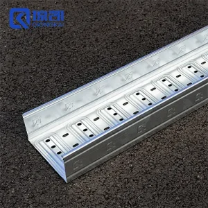
Cost Saving Molded Pre Galvanized Cable Tray Systems
View Specifications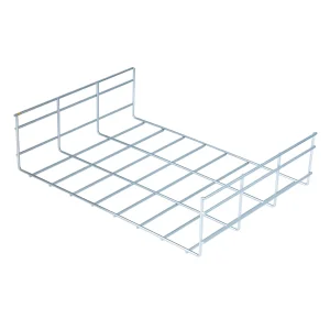
Pre-Galvanized Wire Mesh Grid Cable Tray 400mm
View Specifications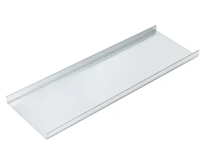
Pre-Galvanized Solid Cable Tray Protective Cover
View Specifications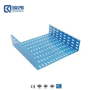
Reinforced Rib PG/HDG Tray RAL5015 Blue 400*100
View Specifications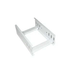
Long-Span Powder Coated Heavy Industrial Cable Ladder
View Specifications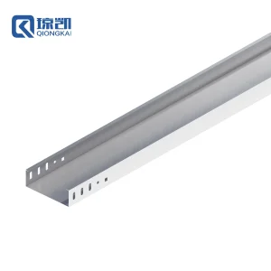
Carbon Steel / SS Trunking Trough Channel 150*50
View Specifications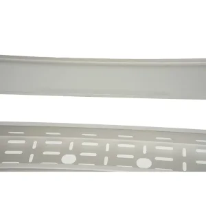
Custom Stainless Steel Cable Tray (Pickled & Passivated)
View Specifications