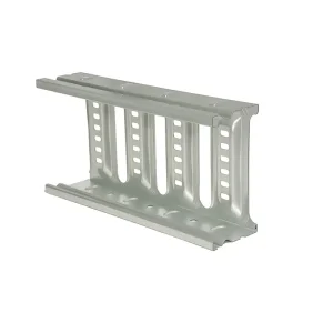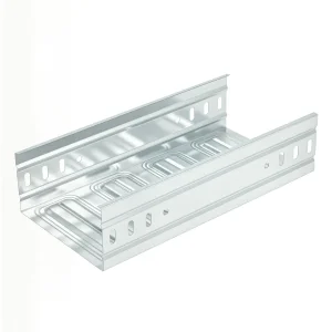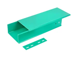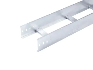
Standard Cable Tray Widths — Precision Engineered Profiles
Browse the most specified metric and imperial channel widths manufactured with automated continuous cold-roll forming lines to exact project tolerances.
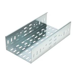
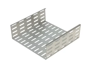
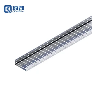
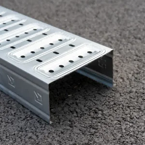
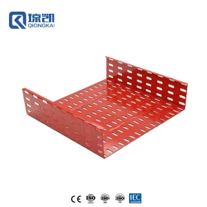
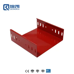
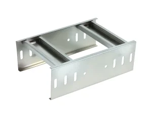
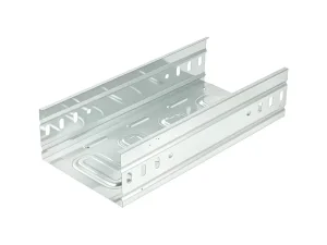
Standard Cable Tray Widths: Engineering Rules & Sizing Dynamics
Proper cable tray dimensioning is the boundary between thermal reliability and catastrophic overheating. Sizing width is not merely a geometric exercise; it balances National Electrical Code (NEC) fill capacities, heat dissipation, and mechanical deflection.
Standard Width Classifications
Global MEP projects demand precise alignment between metric and imperial layouts. Metric widths systematically span 50mm, 100mm, 150mm, 200mm, 300mm, 400mm, 450mm, 500mm, 600mm, 800mm, to 1000mm. These directly translate into imperial systems: 50mm (~2 in), 100mm (~4 in), 150mm (~6 in), 200mm (~8 in), 300mm (~12 in), 450mm (~18 in), 600mm (~24 in), and 900mm (~36 in).
The 40% NEC Fill Ratio Rule
Under NEC Article 392, continuous solid bottom and ventilated trough trays have strict cross-sectional area (CSA) limits. When running control and signal cables, total cable cross-sectional area must not exceed 40% to 50% of the interior tray area. For multiconductor power cables (2000V or less), the sum of cable diameters determines minimum tray width, requiring single-layer laying with physical clearance.
Heat Dissipation & Ampacity Derating
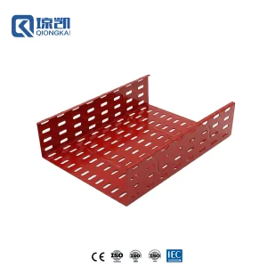
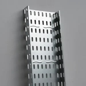
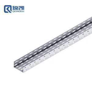
Restricted air volume reduces conductor ampacity. Selecting wider trays (e.g., opting for a 400mm width over a 300mm width with deeper sides) ensures horizontal spacing between heat-generating cores. Ventilated perforations engineered into Qiongkai trays generate a convective chimney effect, allowing cables to retain up to 100% of their open-air current carrying capacity.
| Standard Width (mm / in) | Side Height (mm) | Usable CSA (cm²) @ 40% Fill | Structural Load Class (IEC 61537) | Recommended Industrial Applications |
|---|---|---|---|---|
| 100 mm (4") | 50 / 60 / 100 | 20.0 - 40.0 cm² | Type I (Light Commercial) | Telecom, Cat6A Structured Cabling, Building Automation |
| 200 mm (8") | 50 / 100 / 150 | 40.0 - 120.0 cm² | Type II (Medium Duty Industrial) | HVAC Control Lines, Branch Circuit Power Distribution |
| 300 mm (12") | 100 / 150 | 120.0 - 180.0 cm² | Type III (Heavy Commercial / Data Hall) | High-Density Fiber Trunks, Main Feeder Runs |
| 400 mm (16") | 100 / 150 / 200 | 160.0 - 320.0 cm² | Type IV (Heavy Industrial) | Substation Low-Voltage Cables, Manufacturing Plant Lines |
| 600 mm (24") | 100 / 150 / 200 | 240.0 - 480.0 cm² | Type V (Extreme Heavy Duty) | Transformer Risers, Primary Power Feeders, Heavy Marine |
| 800 - 1000 mm (32"-40") | 150 / 200 | 480.0 - 800.0 cm² | Reinforced Engineered Profile | Power Generating Stations, LNG Terminals, Heavy Infrastructure |
Factory Pricing Architecture & Industry 4.0 Efficiency
How Shanghai Qiongkai Industry dismantles trading intermediaries, optimizing raw material yield and automated forming to give global EPCs unbeatable factory pricing.
Raw Material Cost Mechanics
Factory price for cable tray widths is calculated based on: Coil Slitting Width (Strip Width) + Gauge Thickness (mm) + Zinc Coating Mass (g/m²) + Fabrication Yield. Because strip width increases exponentially with side height and tray base width, continuous automated roll-forming eliminates stamping scrap, saving up to 14% in raw steel consumption versus traditional press-brake methods.
Automated Industry 4.0 Production
Operating across 3 factories with 12 assembly lines and over 60 heavy-duty CNC units in Shanghai, Qiongkai utilizes high-speed automated roll formers. Punching patterns for ventilated slots are executed in-line at 45 meters per minute before profile folding, guaranteeing exact slot pitch uniformity and zero micro-burrs that damage cable insulation jackets.
Supply Chain Resilience & Freight Nesting
A primary driver of landed cost is sea freight volume. Qiongkai designs molded and tapered side-rail options allowing smaller tray widths (e.g., 100mm and 200mm) to nest inside 400mm and 600mm trays during container packing. This increases 40HQ container volumetric capacity by up to 35%, drastically reducing freight per linear meter to European, Middle Eastern, and American hubs.
Global Application Footprint: Standard Widths in Mission-Critical Sites
From high-salinity offshore LNG terminals to mega airports and hyperscale data halls, our standard and custom cable support systems provide rock-solid structural integrity.
Shanghai Hongqiao Airport
Application: Aviation Transport Hub
Solution: Corrosion-resistant Pre-Galvanized and Powder-Coated CT Series cable trunking across 150mm to 400mm widths. Delivered fire-rated cabling routing with zero mechanical failure across high-vibration terminal concourses.
Qatar LNG Offshore Modules
Application: Harsh Offshore Hydrocarbon
Solution: Custom-profiled SS316L and heavy-duty FRP ladder trays in 300mm, 600mm, and 900mm widths. Certified resistance to extreme ambient heat, hydrogen sulfide, and marine salt-fog corrosion.
Hyperscale Cloud Data Halls
Application: High-Density AI Server Infrastructure
Solution: RAL3020 Red & Signal White powder-coated 300mm & 400mm perforated trays with reinforced longitudinal ribs, isolating mission-critical fiber from high-voltage primary busways.
Frequently Asked Questions: Cable Tray Widths & Sourcing
Essential technical, compliance, and ordering questions clarified by Qiongkai's chief structural and electrical engineering teams.
How do I calculate the exact cable tray width required for a project?
Calculate the total sum of cross-sectional areas of all planned cables. For control and multi-conductor cables, apply the NEC Article 392 formula: multiply total cable cross-sectional area by 2.5 (representing a 40% fill factor). Divide this value by your chosen side height (e.g., 100mm) to derive the minimum required interior width. Round up to the nearest standard manufacturing width (e.g., 300mm or 400mm) to allow for 20% future capacity growth.
What is the standard tolerance on cable tray widths according to NEMA VE 1?
According to NEMA VE 1 and IEC 61537, inside width tolerances must fall within ±4.0mm for trays up to 300mm, and ±6.0mm for widths of 400mm to 1000mm. Qiongkai's automated CNC slitting lines maintain tighter factory tolerances within ±1.5mm, ensuring smooth coupler alignment and eliminating sharp internal mismatch steps that abrade pulling conductors.
How does tray width affect structural deflection across long spans?
As width increases (e.g., from 200mm to 600mm), transverse bottom plate deflection becomes significant under concentrated vertical point loads. Qiongkai integrates patented bottom reinforcing ribs and return-flange stiffeners into widths over 300mm. This enhances section modulus (Z), maintaining deflection well within the standard L/200 structural threshold over continuous 3-meter to 6-meter span supports.
When should an engineer specify a cable ladder instead of a perforated tray?
Cable ladders are ideal for heavy-gauge power conductors (typically single-core armored or 4/0 AWG and above) where heat generation is high. Ladders provide unobstructed 100% natural convective cooling, higher rung-clamping resistance during short-circuit electromagnetic repulsion, and easy cable drop-out. Perforated trays are preferred when intermediate cable support, physical shielding, or smaller multicore control runs predominate.
What is the price difference between PG, HDG, and SS316 finishes?
Pre-Galvanized (PG) steel serves as the economic baseline index (1.0x) for dry indoor MEP installations. Batch Hot-Dip Galvanized (HDG, ASTM A123 / ISO 1461, 65-85μm coating) ranges from 1.35x to 1.55x, offering 25+ years of outdoor anti-corrosion protection. Stainless Steel 304 runs approximately 3.2x, while marine-grade SS316L or pultruded FRP typically scales to 4.2x-5.5x, justified by lifespans exceeding 40 years in high-saline and coastal conditions.
Can Qiongkai fabricate customized non-standard tray widths?
Yes. In addition to universal standard dimensions (100mm, 200mm, 300mm, 450mm, 600mm), our automated CNC lines can produce custom widths (such as 125mm, 250mm, 350mm, or 750mm) and asymmetric flange heights without tooling surcharges for production orders meeting minimum batch volumes.
Heavy-Duty, FRP & Custom Cable Management Lines
Explore heavy-duty ladder racks, non-metallic composite profiles, and molded structural trays manufactured to international utility standards.